Supercharge your Raspberry Pi
Get your soldering iron ready
Use the GPIO pins to light up some LEDs
The Raspberry Pi's diminutive size means that it's ideal for making your own embedded devices. This can be a great way of creating small computing devices to solve specific problems, as we saw with the camera controller earlier.

However, there is the slight problem that it can be hard to know what's going on inside your Pi without a screen. Fortunately, the designers of the Pi thought of this problem and have added the facility to get information on and off a Pi without the bulk of usual PC peripherals. This is done via General Purpose Input and Output (GPIO).
(Note: if you have a Pi Zero then its GPIO header is unpopulated – you'll need to solder this in yourself).
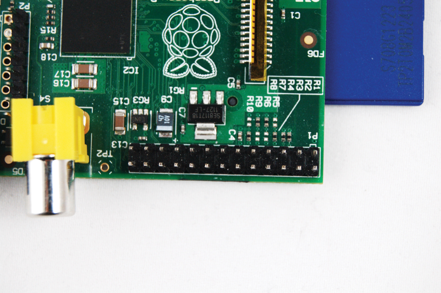
You may have wondered what the spiky pins near the SD card reader are for – well, you're about to find out. This basic circuit can be used to display information from any source, but here we're going to use it to solve a problem we often have at techradar – finding the final byte of the IP address.
This is useful if you want to remotely access your Pi, but can't configure it with a static IP because, for example, you have to move it between networks. Typically, you can find out the first three bytes from the netmask, but the final one can be elusive unless you have a monitor.
We're going to use the gpio program, which is part of WiringPi. You can find out more about this from theWiringPi website.
It comes as source code, so we'll have to unzip it and compile it with:
Get daily insight, inspiration and deals in your inbox
Sign up for breaking news, reviews, opinion, top tech deals, and more.
$ tar xvf wiringPi.tgz
$ cd wiringPi/wiringPi
$ make
$ sudo make install
$ cd ../gpio
$ make
$ sudo make install
We'll also use bc, so install it with:
$ sudo apt-get install bc
Now, that's enough about software – on with the hardware! Just a quick word of warning before we start – it is possible to break your Pi by connecting the wrong wires together, so make sure you double check before powering up.

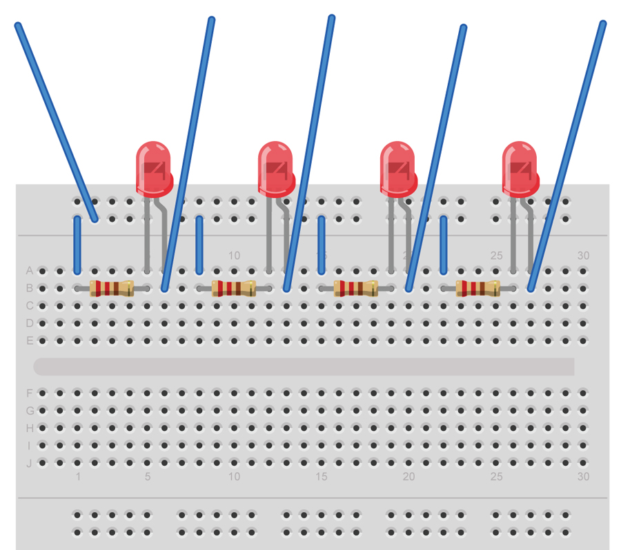
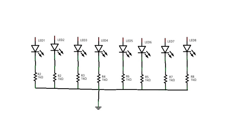
The circuit for this is very simple – you just have to connect each output to the positive leg of an LED, then the negative leg of the LED (shorter) to a 1K Ohm resistor, and finally the other leg of the resistor to the common ground. See figures 1, 2 and 3 on this page for details. Once you have your fully-set-up board connected to your Pi, you can make things happen.
To start with, we'll just use the final pin. This is pin 7 (the layout of the pins doesn't follow a numbering pattern). Open up a terminal, and set it to output with:
$ gpio –g mode 7 out
Then you can turn it on with: gpio –g write 7 1
And off again with: gpio –g write 7 0
If you're like us, you'll do that repeatedly until the novelty wears off.
Once it has, you're ready to run the script. It contains four parts. The first just sets the pins to the right mode and makes sure they're turned off:
pins="7 8 25 24 23 18 15 14"
for x in $pins
do
gpio -g mode $x out
gpio -g write $x 0
done
The second grabs the IP address from ifconfig, converts it to binary, then pads it out with leading zeros, if necessary.
ipaddress='ifconfig eth0 | grep 'inet ' | awk '{print $2}' | cut -f4 -d'.''
binary='echo "ibase=10;obase=2;$ipaddress" | bc'
paddedBinary='printf %08d $binary'
The next part uses cut to extract the part we want from this binary string and outputs it to the appropriate pin.
bit=1
for x in $pins
do
out='echo $paddedBinary | cut -b$bit'
gpio -g write $x $out
bit=$((bit+1))
done
And finally, we tell the script to sleep for five minutes, then turn the LEDs off.
sleep 5m
for x in $pins
do
gpio -g write $x 0
done
That's all there is to it!

Create the showIP.sh script, make it executable with:
$ chmod a+x showIP.sh
Then type sudo ./showIP.sh to display your IP. To get this to run automatically on boot, you just need to add this line to rc.local:
/home/pi/showIP.sh &
See the previous Camera Controller section for details on how to do this.